01
Application consistency
Uneven or insufficient closure application can leave sections of the foil liner without consistent contact around the sealing land. Use the approved bottle and closure method rather than a universal torque figure.
Capping and sealing integration
Control cap application, liner contact, induction sealing and post-seal inspection as one connected closure process.
Answer first
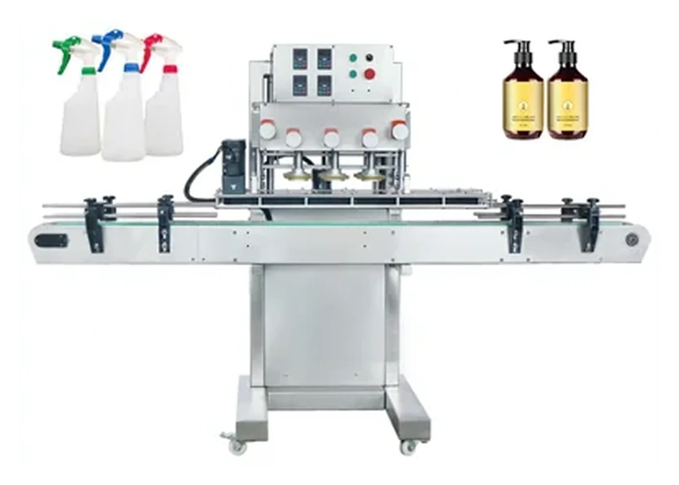
A screw capper should seat the approved closure squarely and apply the condition needed to hold the foil liner evenly against the container sealing land. The capped bottle then passes through the induction sealer under a controlled head position, conveyor speed and power setting. Acceptance should combine cap position, thread engagement, the agreed torque method, foil-seal evidence and recovery after normal line stops.
Line sequence
The best layout depends on the pack and liner system, but each stage should have a named purpose and an observable acceptance check.
| Stage | What must be controlled | Evidence to retain |
|---|---|---|
| Filled bottle arrives | Fill height, foam, splashing, neck-land contamination and bottle stability. | Accepted filled samples, worst-case product condition and normal conveyor presentation. |
| Cap presentation | Correct cap and liner identity, orientation, square placement and clean thread start. | Approved component references and visual examples of acceptable placement. |
| Screw capping | Cap height, thread engagement, bottle restraint, chuck or spindle contact and the agreed torque method. | First-off samples, recorded settings and pre-seal torque or cap-position results. |
| Induction sealing | Sealing-head selection, air gap, bottle alignment, conveyor speed, power and exposure time. | Sealer recipe, operating window and sealed sample results for each format. |
| Conditioning and inspection | Cooling or dwell period, foil bond, liner release, leakage method, cap condition and opening evidence. | Named test timing, pass/fail examples and the action taken for failed packs. |
| Stop and restart | Bottles left under or near the active sealing field, capper/sealer interlocks and first-off verification after restart. | Documented recovery sequence and approved restart samples. |
Critical variables
Induction sealing depends on the complete pack. The capper creates the liner contact condition; the sealer supplies energy; the bottle, cap, foil and product determine the result.
Uneven or insufficient closure application can leave sections of the foil liner without consistent contact around the sealing land. Use the approved bottle and closure method rather than a universal torque figure.
Product residue, damage, moulding defects or an incompatible sealing surface can prevent a complete bond even when the sealer setting is stable.
One-piece and multi-piece liner systems can behave differently during heating, cooling and cap removal. Confirm the liner supplier’s application instructions and test the actual closure.
Tall, spouted or child-resistant closures can change the distance and field path between the sealing head and foil. The sealer supplier should confirm the appropriate head arrangement.
Bottle centreline, pitch, line speed and stops affect exposure. Accumulation should not allow capped bottles to remain in an unsafe or uncontrolled position under an energised head.
Removal torque may change after heating and liner compression. If re-torquing is considered, it should be justified by the closure requirement and validated as part of the line rather than added automatically.
Authoritative reference
Enercon explains that consistent cap application helps maintain contact between an induction liner and the container lip. The approved operating window, torque method and finished-pack test must still be established for the actual pack.
Use the source to understand the relationship between cap application and liner contact, then follow the closure and liner suppliers’ limits for the real pack.
Use conditioned removal-torque evidence and seal inspection to understand the post-seal pack rather than assuming the pre-seal reading remains unchanged.
Buyer questions
The answers depend on the exact bottle, cap, liner, product and sealer configuration.
No. An induction sealer supplies energy to the foil liner; it does not correct cross-threading, a high cap, an incompatible neck finish or uneven liner contact. Correct the capping condition first, then prove the sealing window with representative packs.
No. The required application condition must come from the approved closure, liner and container system. Excessive tightening can distort the pack, damage a liner, mark the closure or create difficult opening. Use a validated range and finished-pack evidence.
Often it is useful to record both, because liner heating and compression can change removal behaviour. Keep pre-seal and post-seal results separate, record the elapsed time and use the same instrument and method.
It normally follows cap application and any pre-seal checks that protect the process. The final position should provide stable bottle transfer, the correct head clearance, safe stop handling and space for downstream inspection or rejection.
They can share a line where conveyor height, bottle stability, pitch, speed control, accumulation and interlocks are compatible. Prove the complete sequence under normal running, planned stops, replenishment and restart conditions.
Supply production bottles, lined caps, normal component lots, product-equivalent filled samples, approved good packs and the liner supplier’s application information. Include the least stable bottle and every materially different cap or liner format.
Related guidance
Separate application, immediate removal and conditioned removal evidence.
Check liner identity, compression, seated height and finished-pack behaviour.
Combine visual, dimensional, functional and production-run evidence.
Send the bottle, lined closure, product condition, target output, current torque method and sealer information so Lancing can review the capping and line-integration requirements.
Buyer decision support
Any proposed re-torquing stage should have a stated purpose, approved incoming package condition and separate acceptance evidence. The original application, sealing process and later opening test must remain traceable rather than being reduced to one final torque number.
Record whether the proposed check or adjustment is before sealing or after the approved process and cooling condition. Do not borrow a timing rule from another pack.
Keep examples that have not received the second operation so its effect can be compared with the original route.
A changed reading does not, on its own, prove improved foil bonding, leakage performance or tamper condition. Apply the agreed package checks.
Use the re-torquing decision framework before adding equipment. The torque-retention guide helps separate the effect of time and sample condition from a deliberate additional tightening operation.